
Pay attention to the official Wechat platform and learn more about Epp


DC motor is featured with wide range of speed regulation and smooth stepless speed regulation. The duty cycle of PWM pulse signal determines the average voltage output to DC motor. By adjusting the duty cycle, the output voltage can be adjusted continuously. Based on AT89S51 single chip microcomputer, the design method of DC motor speed regulating and measuring system is presented. The main circuit structure, driving circuit design and system software design are given. It takes full advantages of single chip microcomputer, and has the characteristics of high frequency and fast response.
DC motor, a common driving equipment in industrial production, has good starting and braking performance. In the early days, the control of DC motor was based on analog circuit, which was composed of operational amplifier, nonlinear integrated circuit and a few digital circuits. The hardware part of the control system is complex, the function is single, and the debugging is difficult. With the single chip microcomputer control system, many control functions and algorithms can be completed by software technology, and it provides greater flexibility for DC motor control and enables the system to achieve higher performance.
1. The principle of PWM DC speed regulation based on single chip
PWM (pulse width modulation) is a technology which uses the digital output of microprocessor to control the analog circuit. It is widely used in many fields such as measurement, power control and transformation. Pulse width modulation (PWM) is an analog control method, which modulates the bias of transistor base and changes the conducting time of transistor according to the change of corresponding load. It is a very effective technology to control the analog circuit by using the digital output of microprocessor.
A fixed frequency to turn on and off the power supply, and change the length of "on" and "off" time in a cycle as required. By changing the "duty cycle" of the voltage on the armature of the DC motor, the average voltage can be changed to control the speed of the motor. Therefore, PWM is also known as "switch driver". The duty cycle of the PWM determines the average voltage output to the DC motor. Therefore, by adjusting the duty cycle, the output voltage can be adjusted continuously.
2. Main circuit design of speed regulation and speed measuring
The whole system is composed of input circuit, PWM modulation, speed measuring circuit, driving circuit, control part and display part, PWM modulation uses AT89S51 single chip microcomputer to adjust frequency and duty cycle through software.
2.1 Design solution of DC motor speed regulation
The drive circuit uses the optocoupler isolation protection circuit, and the control part is composed of the single chip microcomputer and the peripheral circuit to realize various control requirements. The peripheral circuit mainly completes the collection, operation and speed control of the input signal, and the display part uses the four digit common positive nixie tube.
In the aspect of hardware, STC89C51 single chip microcomputer is the core, and the minimum system is composed of reset circuit, crystal oscillator circuit, drive circuit, speed measuring circuit, keyboard and LED display module. In the software, the output of PWM pulse signal, the data transmission of keyboard and LED display are generated by programming with C51 language. By adjusting the given value of the speed gear through the keyboard, tracking is realized according to the given value, displayed on the LED display, and finally PWM pulse signal is output by the single chip microcomputer. The speed is fed back to the CPU through the speed measuring circuit and displayed on the LED display through the CPU, so as to achieve the desired set speed.
2.2 Display circuit design
LED adopts the dynamic display mode, the actual spped of the motor is displayed by the four digit nixie tube, which is convenient for the monitoring of the system. The system uses the four digit common positive nixie tube, 9012 triode switch circuit to drive and control the display of the nixie tube.
2.3 Reset circuit
The reset circuit of single-chip microcomputer is like the restart part of computer. When the single-chip microcomputer system is running, the program inside the reset button is automatically executed from the beginning. The reset circuit adopts two ways of power on automatic reset and manual reset. C3, R21 and S1 form the reset circuit.
2.4 Clock circuit
The clock circuit of the system is designed in the internal, and using the internal oscillation circuit of the chip. There is a high gain inverting amplifier in AT89 series single chip microcomputer and it is used to form the oscillator. Pins xtal1 and xtal2 are the input and output of the amplifier respectively. The amplifier, together with an off chip crystal resonator forms a self-excited oscillator. The external crystal resonator and capacitors C1 and C2 form a parallel resonant circuit, which is connected in the feedback loop of the amplifier.
3. DC motor driving circuit design
The direct output control signal from single-chip microcomputer can not directly drive 12V DC motor. At present, most of them are driven by H-bridge. In order to make it easier, the driving module uses optocoupler to isolate the control circuit and the main circuit, so as to achieve the protection function. U3 outputs PWM control signal to drive motor through triode reverse phase to realize motor speed regulation.
4. Speed measuring circuit design
The speed measuring module is composed of U-type photoelectric switch, turntable and peripheral circuit. When the motor rotates, it drives the turntable to rotate. There are eight small holes on the turntable. When the turntable rotates for one week, eight pulse signals are generated. Therefore, the physical quantity of motor rotation can be converted into the changed pulse signals, which are driven by Q5 switch and transmitted to the MCU to interrupt p3.3 for counting, so as to realize the monitoring of motor speed.
The common photoelectric speed measurement method is used in the design. The specific method is to fix a disk on the motor shaft and use the U-type optocoupler in the speed measurement module. The pulse signals are generated through eight circular holes on the turntable. When the motor is turned to the hole, the light-emitting diode irradiates the light on the photosensitive triode through the gap, and the triode is on, otherwise the triode is off.
The installation of U-type photoelectric switch and rotary table is : fix the rotary table on the motor shaft, install the U-type optocoupler, insert the optocoupler into the rotary table, and fix it with screws. The side of the rotary table shall be installed in the middle of the groove of the U-type photoelectric switch.
5. Software design of speed regulation and measurement
The system software is developed in C51 language and designed in modularity. Timer interrupt working in 16 bit counting mode, digital display, PWM control. The external interruption is triggered by the negative edge to realize the measurement of motor speed.
6. Summary
The design of speed measurement and speed regulation system based on single chip microcomputer is to convert the input signal into output control signal and adjust the speed of DC motor through driving circuit, and to monitor the speed of DC motor in real time. The PWM control technology can achieve high precision speed control. The photoelectric switch is used for speed measurement, which can easily realize the speed detection. Therefore, the speed measurement and speed regulation system of DC motor designed should have the main circuits of speed input, detection, display, pulse width modulation, motor drive, etc., so as to control and display the motor speed.
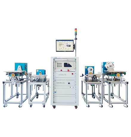
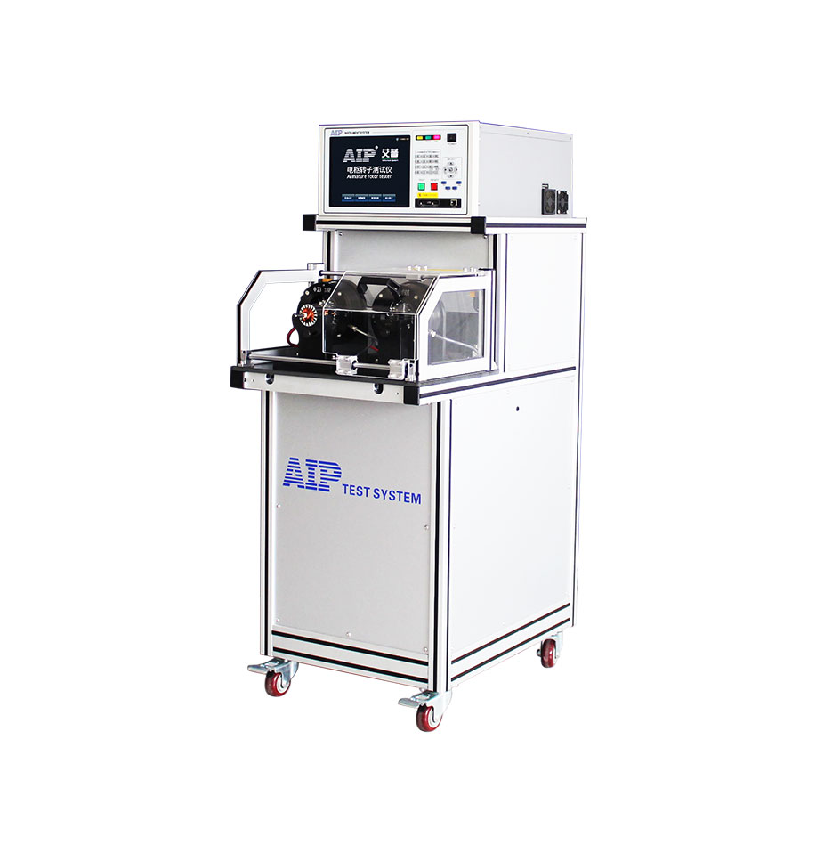
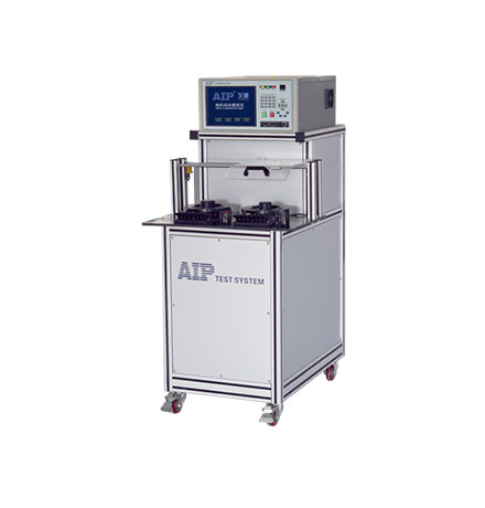
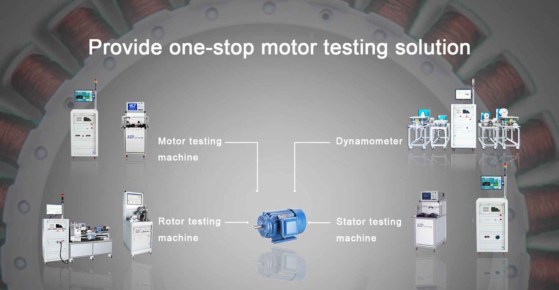
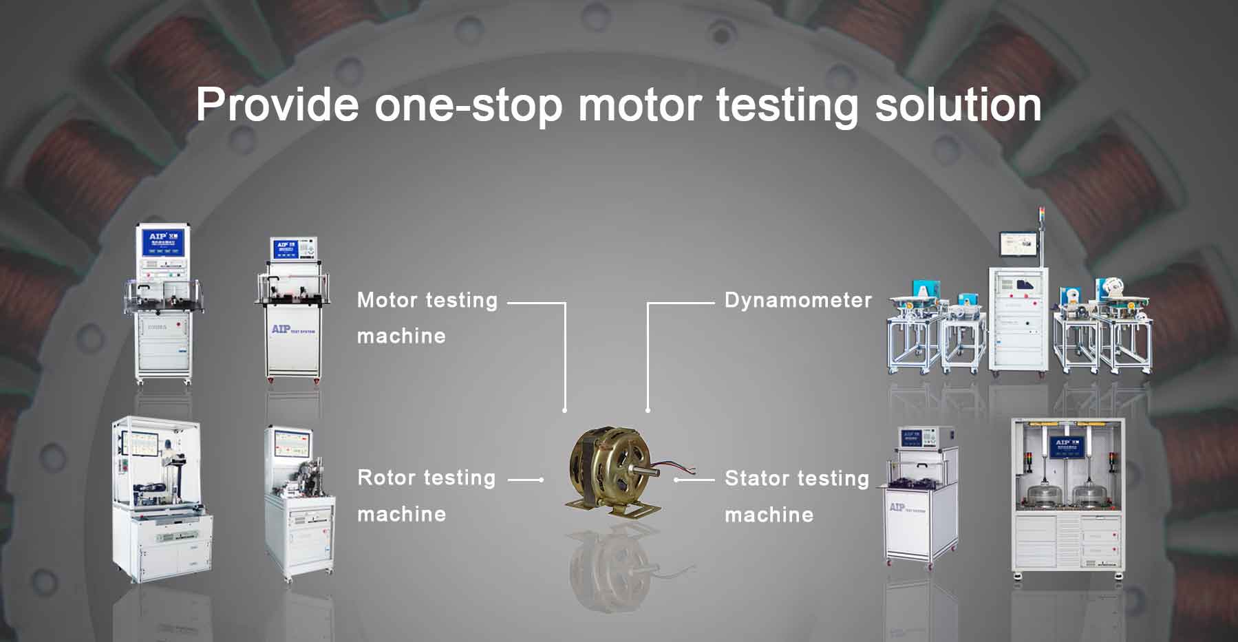
Qingdao AIP Intelligent Instrument Co., Ltd. focus on motor testing and provide one stop motor testing solution. AIP has always been adhering to the enterprise concept of "customer-oriented, striver-based" and constantly improving the motor testing solutions, and fully participating in the global motor testing industry.